What's it about?
The use of high-power continuous wave (CW) lasers in the emerging directed energy (DE) market has put greater emphasis on the quality of optical coatings. These coatings (both high reflectance and anti-reflection) require high damage thresholds for use at irradiances up to and greater than 1 MW/cm2. The challenge in the coating process is to minimize the number of coating defects that can contribute to absorption and eventual coating failure. The industry lacks standardized testing to detect possible defects at the required irradiances for DE optics. To aid in the development of coating designs and production techniques for DE related optics, we have constructed a high-irradiance Ytterbium fiber laser-based scanning metrology system to detect absorbing defects in DE optical coatings. Defects are detected by their localized thermal heating creating a hot-spot. The goal of this work is to continually improve the coating, increase the laser damage threshold, and contribute to a standard for the testing and validation of directed energy optical coatings.
Keywords: directed energy, laser damage, coating defects.
1. INTRODUCTION
The advancement of laser technology has brought continuous wave (CW) lasers with average powers and electrical efficiencies unheard of just a decade ago. These lasers, typically fiber-based, which can operate in the several tens of kilowatt range, have become ubiquitous and available at price levels that have made new applications economically feasible. These applications include high speed precision cutting and welding in industry, as well military applications in the form of directed energy weapons. Directed energy weapons work by concentrating the high power from a CW laser onto the target, causing catastrophic heating, thus disabling or destroying the target. A number of countries are investing in directed-energy (DE) weapons systems based on high-power lasers. In the United States, the Department of Defense (DOD) has a number of DE development programs underway, requesting at least $578 million in FY2022 for unclassified DE research, development, test, and evaluation (RDT&E) and at least $331 million for unclassified DE procurement. The DOD roadmap outlines a plan to increase power levels from around 150 kilowatts (kW), as is currently feasible, to around 300 kW by FY2022, 500 kW by FY2024, and 1 megawatt (MW) by FY20301. At the global level it is estimated the total market for directed energy weapons is $15 billion in 2020 and is projected to reach $51 billion by 20262. This increase in interest in directed energy optics has yielded increased interest in directed energy capable coatings, both high reflectance and anti-reflection, with zero tolerance for in-field failures. This has spurred coating facilities to fine tune the coating process to attempt to eliminate coating defects, predict potential failures, and validate coating quality before being delivered. In this paper we will describe our path to addressing the needs of directed energy coatings and to identify the sources of potential failures of these high demanding optics.
2. REQUIREMENTS ANALYSIS
At Optimax, our interest is in developing a facility for in-house laser-induced damage testing (LIDT) in support of coating
process R&D. In designing the test facility, we must consider all of the requirements drivers, including use cases, characteristics of the DE laser and optics, and laser damage mechanisms.
2.1 USE CASES
2.1 Use Cases
There are three internal use-cases that drive the need for LIDT; in all use cases we require an ability to routinely test at 150 kW/cm2 irradiance, with maximum testing up to 500 kW/cm2:
1. Process Improvement R&D. Understand the contributors to laser-induced damage (LID) and the underlying mechanisms that drive it. Use this knowledge as feedback to the coating process, and to develop refined LID predictive mechanisms.
2. Quality control. Perform ongoing LIDT as part of production, typically on witness samples (may include destructive tests).
3. Production testing of high-value optics. Qualify DE optics (often very expensive) to assure they will meet LID performance requirements. This must be done without damaging the optic. This is intended for pre-qualification prior to testing by a qualified external test lab.
Each use case contributes to the requirements for the overall test facility.
2.1 Characteristics of DE Lasers and Optics
High-power DE lasers operate in CW mode, with pulse lengths from seconds to minutes duration. They are comprised of arrays of fiber or semiconductor-diode lasers that are combined into a single, high quality beam using spectral beam combining - an approach where many laser beams, each with a slightly different wavelength, are superimposed onto a single beam using a device with angular dispersion such as a prism or grating. The power in the resulting beam is the sum of the powers of the individual beams.
DE optics include both transmissive and reflective elements. Transmissive elements, used in the lower-power portions of the DE system, have AR coatings comprised of 4 – 200 layers of proprietary materials. The higher-power portions of a DE system typically use multilayer mirrors, comprised again of 100s of layers and designed to efficiently reflect the DE laser over a designed spectral bandwidth (the photonic stopband). Both types of coatings require laser-induced damage testing.
There are many different deposition technologies used to create coatings for Directed Energy: Ion-Beam Sputtering (IBS), Reactive Evaporation, and Plasma-assisted Evaporation. However, IBS tends to be the technology of choice due to requirements at multiple wavelength (making coatings very thick) and high reflectivity (low scatter). In addition, IBS has low absorption and high CW laser damage threshold in the NIR wavelength region typical of DE systems.
2.3 Laser Damage and Wavefront Aberration Mechanisms
Inherent to all coating processes are defects – that is, deviations from ideality. These can include:
- Surface defects in the underlying substrate material
- Variance from the design thickness for a layer or layer-stack
- Variance in the index of refraction (and absorption coefficient) of the coating material from the design value
- Stress-induced distortions in the coating
- Nanometer-scale inclusions and bubbles (distributed through the coating volume)
- Microcracks and dislocations
- Scratches and digs in the coating surface
- Micron or larger scale inclusions and bubbles in or on the coating layer
Further, there may have been design tradeoffs in the coating (for instance, accounting for laser bandwidth and/or multiple
wavelengths) that make it non-ideal over part of the operating range.
For CW lasers (pulse length greater than ~ 1 microsecond), thermal effects dominate over high-field effects observed in short-pulse lasers (e.g., dielectric breakdown, avalanche ionization, multiphoton absorption)3. Hence, if these defects absorb energy it will give rise to an increase in temperature, leading to thermal expansion, strain, birefringence, moving of internal defects, cracking, and melting. If these mechanisms impact performance beyond the specification, or if they are a precursor to further damage, they must be characterized by testing.
There are four general four damage scenarios to consider:
1. Highly-absorbing materials (e.g., metal mirrors)
2. Transparent materials (transmissive elements and coatings)
3. Absorbing inclusions in the coating
4. Surface finish imperfections (scratch/dig, roughness)
The first scenario is not relevant to DE optics (metal mirrors are not usable at such high incident power). Our interest is primarily in coating damage in multilayer films, which are by design extremely low absorbers of the incident laser light. Hence, it is the last three scenarios that are of interest in LIDT: Absorption in transparent materials characterizes the “pristine” coating, while absorption in inclusions and surface finish imperfections address realistic scenarios that occur in a statistical manner throughout the coating.
In defining laser damage, we must consider any laser-driven mechanism in the optical coating that degrades the functional performance of the DE system4. Sometimes termed functional damage threshold testing (FDT), this is usage dependent. For instance, the National Ignition Facility (NIF) at Lawrence Livermore National Labs (LLNL) has established specifications that allow a certain number of damage sites below a threshold diameter and morphology/type (they do not grow over time). LLNL has determined that the laser performance is not degraded by these defects.
Conversely, some mechanisms may degrade transient performance but not produce permanent damage: For instance, thermal absorption in defect inclusions may induce transient, localized phase errors in the coating with transverse size of order the thermal diffusion length. If the functional performance of the DE system is impacted by such phase errors then the LIDT testing must be capable of identifying and characterizing them.
2.4 Laser Requirements
A baseline requirement for the facility is to fully support testing per ISO 21245-2:2011 (while we do not intend to operate a qualified test facility , we intend to follow the protocols internally). A good review of the motivation and methods behind this standard may be found in a paper by Shao4. Briefly, the protocol calls for an ability to focus a laser of known, adjustable power and spot size (≥ 800 m) on the unit under test (UUT), and to be able to scan the spot across the unit. For the single-shot (1-on-1), multi-shot (S-on-1), and ramp (R-on-1) tests the laser is positioned at known, fixed points on the UUT. Assuming coating uniformity, this provides statistical sampling of the coating (including defects). For the raster-scan test the laser is scanned in a serpentine pattern across the device at a known rate and with a known cross-track overlap (typically set as the beam width at 90% intensity for a Gaussian beam). The raster scan is performed with fixed spot size and intensity, and programmable dwell time. However, it can be repeated with other intensities.
While the ISO standard was developed in the context of pulsed lasers, much of it transfers readily to CW systems provided that care is taken in configuration and data analysis. Since the test laser is not likely capable of producing operating DElevel irradiances across the entire optic, an LIDT facility will use a lower-power laser focused to a spot to attain the same irradiance. In the long-pulse (thermal) regime one must account for thermal transport processes to be sure the test mimics the real system operating conditions. For a coating material of diffusivity D [cm2/s] illuminated for time , the diffusion length L [cm] is3:
![]()
For glass (D ~ 0.0075 cm2/s) and a laser pulse duration of 1 sec we obtain a diffusion length L ~ 1.7mm (L is a radius, so the hot-spot diameter is ~ 3.4 mm). This will not increase indefinitely with pulse length: Eventually the temperature rise reaches a steady state as the diffusion boundary matches with the unheated area of the coating (for hot spots we observe this to happen in 1-2 seconds). To further illustrate the difference between the short-pulse and CW regimes, consider Figure 1, which shows the thermal diffusion length for a series of increasing pulse times. A 1 sec pulse corresponds to an approximately 1 m diffusion length – still smaller than any realistic laser beam diameter and just approaching characteristic defect sizes. At 1 msec the diffusion length is already over 100 m, creating a region in the surrounding material where the morphology and optical properties may be changing and interacting with the laser beam. In summary, the small focused spot of an LIDT system has different thermal boundary conditions compared to a full-aperture DE beam, and the long laser pulse duration means we are not interacting with a static UUT. These factors must be kept in mind when interpreting the results.
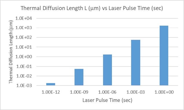
Figure 1 Thermal diffusion length for a series of increasing pulse times (1 psec, 1 nsec, 1 sec, 1 msec, and 1 sec).
A 1 sec pulse corresponds to an approximately 1 m diffusion length
Another constraint on the test laser is that the beam diameter should be larger than any inclusions. These range from 1-20 μm in diameter (the maximum coating thickness), so even a 100 μm laser spot will meet this requirement. Note that thermal diffusion lengths also matter when it comes to heating inclusions. As discussed by Papernov5, for very small absorbers a high surface-to-volume ratio leads to efficient heat removal by conduction, whereas for large absorbers the lower surface-to-volume ratio leads to less efficient volumetric heating by the laser. In between these ranges, for a given pulse length τ, an absorber subject to maximum heating has a radius approximately equal to the thermal diffusion length L.
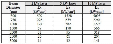
The take-away from above is that the laser spot diameter relative to the thermal diffusion length is an important design parameter of the test system. Table 1 shows the average power density EA in a focused laser spot of a given diameter (from 100 μm to 3 mm) for the input laser power indicated (note that for a Gaussian beam the peak intensity will be two times the average). A 3kW beam focused to a 1 mm diameter spot produces an average irradiance of 382 kW/cm2 (Gaussian peak 764 kW/cm2), well above our standard test requirements. Note, however, that the 1 mm spot is of same order of size as the diffusion length. If it were much smaller we could treat the heat source as a very thin cylinder diffusing into the volume, while if it were much larger we would approximate the full-aperture DE conditions. In this intermediate regime we may need to account for beam size effects using model-based analysis.
Table 1. Average irradiance EA [kW/cm2] at the UUT for a given beam diameter and laser power [kW]
3. TEST SYSTEM
The testing setup for locating measuring absorption hot-spots is shown in Figure 2. The laser is a 3kW ytterbium fiber laser operating at a wavelength of 1070 nm.
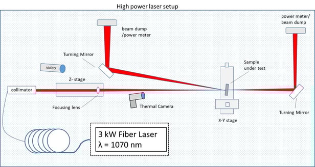 Figure 2: Schematic of the high-power laser set-up for testing high power coatings
The laser is focused onto the sample with a 1-meter focal length lens mounted on a Z-axis stage, which allows adjustment of the laser spot size of approximately 0.5- 2.0 mm in diameter at the sample. The size and profile of the laser spot is monitored using an beam profiler; a sample profile for a 1 mm spot is shown in Figure 3. The spot size range and the variable power level of the laser gives a testing irradiance range of 6 - 3000 kW/cm2.
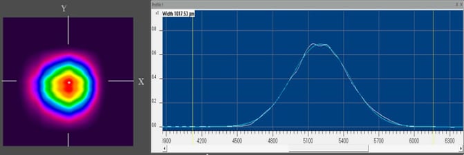 Figure 3: The laser spot shape and profile for a 1 mm spot size.
4. DEFECT TESTING RESULTS
4.1 Hot Spot Scanning
An example T map is shown in Figure 4. This map allows us to identify region of heating/absorption and therefore a
potential defect site.
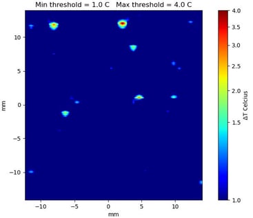
Figure 4: An example hot spot map after laser scanning sample.
Once hot spots are located, they can be visually observed using a microscope. Figure 5 (a) is an example of a defect observed under a Nomarski phase-contrast microscope. This example defect has a size of approximately 10 μm as measured by the microscope. Additional details of the defect can be observed using an electron scanning microscope as shown in Figure 5 (b).
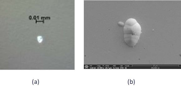 Figure 5: An example defect shown by a Nomarski microscope (a) and then a top down scanning electron microscope (b)
Using a cross-sectional scanning electron microscope additional visualization of the defect is attainable and is shown in Figure 6.
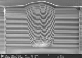
Figure 6: A cross-sectional SEM scan of the defect found in Figure 4.
This cross-sectional view shows the location of the defect in relation to the multi-layer coating. From the image it is evident that the defect in question is sitting on the substrate and the coating layers are deposited on top of it - indicating a precoating contaminant. Additional analysis by energy dispersive X-ray spectroscopy identified the defect as being an organic contaminant. By finding the source of the contamination the coating process can be improved and reduce the occurrence of hot spots on the optic.
4.2 Hot Spot Irradiance Scaling
The temperature behavior as a function of irradiance of these hot spots are under investigation. In high laser power applications, the mirrors within the laser system must withstand certain irradiance for long periods of time. The relationship between temperature rise and irradiance is an import parameter to understand. In an effort to avoid pushing the testing to catastrophic failure predictive knowledge of the temperature rise at high irradiances based on lower irradiance measurements is advantageous.
Using three different samples with several hot spots each, a data set of temperature rise versus irradiance was gathered. The results are shown in Figure 7.
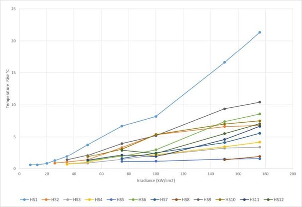
Figure 7: Results of measuring temperature change of hot spots vs irradiance.
Twelve hot spots were measured at irradiances ranging from 8 – 176 kW/cm2. Different hot spots had different levels of detectability. One (HS1) was detected at a low irradiance of 8 kW/cm2 while HS8 was not detectable until an irradiance of 150 kW/cm2. In all cases except HS1 the temperature rise seems to follow a linear relationship to irradiance. The cause of the difference in hot spot detectability and temperature slope is still under investigation for parameters such as size and composition. Hot spots and potential damage can occur at very low irradiances due to post-coat contamination on the sample. This puts the sample at risk for damage during testing. Testing at lower irradiances has the advantage to avoid damaging the part while predicting its behavior.
5. FUTURE WORK
5.1 Evolve Test Standards for Directed Energy Optics
The ISO 21254 standard6 for laser induced damage testing outlines test procedures that “are applicable to all combinations of wavelengths and pulse lengths”. This is true, and the ISO test protocols remain relevant. However, as discussed herein and as acknowledged by the community, CW lasers can introduce many complexities related to thermal diffusion in the coating and coating substrate. Even for a small defect, laser pulse times greater than several milliseconds may generate heat-diffusion regions whose boundary is of order of the test-laser beam diameter (100’s of microns). The laser heating is no longer an “impulse response” of the defect, but rather a complex, space- and time-dependent interaction. Further, for typical coating thicknesses of 10 m, the diffusion boundary may be far larger than the coating thickness – introducing heat-transfer boundary conditions at the upper surface (atmosphere) and the lower surface (optical substrate) of the coating.
Hence, unlike the short-pulse regime, CW laser test probes are characterizing a region that can be changing over the duration of the laser pulse: thermal energy is flowing through and transforming the material and (in some cases) morphology, and the laser-material interaction may be changing as well. Accounting for this added complexity requires more detail in the measurement process (discussed below), and likely more sophisticated analysis software that incorporates physical models.
There is continuing need for an industry standard with broad and pervasive community input, and it is important that such initiatives are supported. There are ongoing community efforts to address these issues. For instance, ANSI/ASC OP (Accredited Standards Committee for Optics) task force 7 (TF7 "laser applications") is working to develop a functional test method, and ISO TC172 SC9 is working to update the ISO 21254 standard - including developing more standardized test methods and damage prediction algorithms as well as a more functional laser induced damage threshold that can be application dependent.
5.1 Evolve Test Standards for Directed Energy Optics
While high-power laser testing with thermal imaging can identify hot spots that are, presumably, associated with defects, it cannot characterize the defects themselves. Currently we pre-scan the UUT using a Nomarski or other microscope to map defect locations. We are upgrading this with confocal/laser scanning to characterize the defect morphology and threedimensional position in the coating stack; this capability will be integrated directly into the laser test system. We are also developing methods to more accurately index location on the UUT from one instrument test to another so as to facilitate correlation of disparate data sets.
We currently perform pre- or post-scanning of UUT coatings using photothermal common-path interferometry (PCI). This can identify regions of anomalous absorption in the coating, which can then be correlated with hot spot and microscope scan data. We plan to incorporate PCI (or other interferometric pump/probe method) into the laser test system as a dynamic measurement of transient phase distortions due to thermal absorption.
Our overall goal is to fully characterize thermal absorption and response at defect locations – both temporally and spatially. It is conjectured that some hot spots will behave differently based on material composition, morphology, and thermal contact (or lack thereof due to voids) with the surrounding coating. With this information we can identify the more harmful defects and concentrate process improvement efforts towards mitigation. Further, we hope to be able to identify and predict laser damage at lower irradiances to the UUT. In addition to PCI, we are investigating several other diagnostic approaches including:
- Thermal microscope. We have procured a higher resolution LWIR camera system that can resolve 28 μm at up
to 125 frames per second. This will allow us to resolve hot spot heating and thermal diffusion over time. - Pump-probe techniques. For even higher spatial and temporal resolution we are exploring techniques such as
Raman thermometry, spectral pyrometry, and reflectometry. The concept is to scan a very narrow laser probe
beam over the interaction region to delineate the thermal behavior.
As a practical matter, control of post-coat surface contamination (dust, cleaning artifacts, and handling damage) on the
UUT is extremely important. While we have implemented best practices in contamination control, it is never perfect.
Hence, we have incorporated a dedicated dark-field scanning camera into the LIDT system to constantly monitor for
uncontrolled surface contamination so as to avoid skewing the measurement results.
We are also investing in data management and data analysis. All measurement data is being normalized and time-indexed
in a data warehouse specifically design for metrology data. This will facilitate correlation of multiple measurements and
changes over time. As part of the data analysis suite we are developing tools for image registration and distortion
correction, automated feature identification, and time-series analysis. Finally, we have started a Multiphysics modeling
and simulation effort to both generate insight to drive our tests and to support model-based analysis of data.
6. CONCLUSIONS
We have built a high-power CW laser scanning system to locate defect driven hot spots in the coatings of directed energy optics. We can further examine these hot spots by imaging the defect, finding its location within the coating, and determining its chemical composition. This allows us to improve our high-power production coatings as well as assist in research and development projects. These continuous improvement efforts are helping us to address the evolving, demanding needs of the directed energy market. In addition, these investigations are helping drive and evolve test standards specifically for directed energy markets, as well as the growing application of high-power industrial laser markets.
References
[1] Defense Primer: Directed-Energy Weapons, Congressional Research Service, 2021.
https://crsreports.congress.gov/product/pdf/IF/IF11882
[2] ReportLinker,” Global Directed Energy Weapons Market to Reach $51.1 Billion by 2026”,June 25, 2021,
[3] Wood, R. “Laser-induced damage by thermal effects”, in Ristau, D., [Laser-Induced Damage in Optical Materials],
CRC Press, New York, 9-23 (2015).
[4] Shao, J. “Measurement and detection of laser-induced damage”, in Ristau, D., [Laser-Induced Damage in Optical
Materials], CRC Press, New York, 155-182 (2015).
[5] Papernov, S. “Defect-induced damage”, in Ristau, D., [Laser-Induced Damage in Optical Materials], CRC Press,
New York, 25-74 (2015).
[6] ISO 21254-2: Lasers and laser-related equipment – Test methods for laser-induced damage threshold – Part 2:
Threshold determination. International Organization for Standardization, Switzerland, (2011).
Optimax Systems, Inc., 6367 Dean Parkway, Ontario, NY 14519
Terms of Use: https://www.spiedigitallibrary.org/terms-of-use